A Nuttycellist's Monologue: A new camera: My old camera, the model S100 of Canon, has acted up recently. The lens was kept out even when the switch was off. The display said it was a...
Hi Shin
Yes the Canon s100 was a great camera , I have still have my S120 model which has the CMOS sensor as well as a Canon G15 . Both camera served me well on trips to Asia for many years. The G15 has a bigger glass lens which gives a better light capture area for night or dim lighted conditions.
On my travel I snapped as many pictures of areas I visited and many years later review them. I find that even being there I missed a lot of details until I reviewed the pictures such as picures of store fronts as the bus I was riding passed by.
73 wayne Cheng , Vanvouver,BC on Face Book under "wayne cheng"
Minima Project
Gathering parts,testing and building new equipment as we build a Ham radio Transceiver.
Sunday, 13 January 2019
Wednesday, 8 July 2015
part filter bandpass testing
Made a transformer to match the 100 Ohm output impedance of the Adruino controlled AD9850 DDS board to the 50 Ohm input of the filter. the output is loaded with 50 Ohm (parallel two 100 Ohm resistors)
Fired up the RF generator and used my $20 dollar ham fest bought 20Mhz oscilloscope as the detector.
look like the band pass is around this frequency.
the reading was barely there on the scope . the sensitivity of the scope at max 5mV/cm and the 20Mhz range at the edge. Boy, this is going to be unusable data collecting.
I just step through the RF generator range at 100 Hz steps from 19.994 to 19.999 mhz.
the scope blurr shows it blinked very fast indicating the filter is sharp.
I must add an amplifier to this to buffer and amplify the signal.
Took a quick reading on the input side of the filter and the output side readings. te input was 150mV and the output was 60mV.
20 Log 60mV/150mV=-7.96 db loss
time to build an amplifier with 50 Ohm in and 50 Ohm out. remembered VK5TH site has one circuit.
http://vk5tm.com//homebrew/dds/dds.php
click on the schematic to enlarge and click back to the blog
click data t o view
Saturday, 4 July 2015
 | ||
| Toner resist on copper board |
Finally received the 100 20Mhz crystals from Malaysia after a month wait at 9 cents a piece with shipping included.
I begin the project by making a G0UUR board for testing the crystal frequency and make a list and choose close matched crystals. I needed 8 crystals for the band past filter.
 | |||||
| First test of the oscillator stability |
First test of the oscillator circuit on the etched PC board and found the oscillator level a bit low and erratically quit. It was caused by two voltage divider capacitors being too large a value from the base to the emitter and ground . I changed the values from 1000pF to 220pF and then the circuit worked very stable and the frequency didn't drift.
Ready to tackle the 99 crystals ( short shipped one ) and write down the value and label the crystal.
Got about 75 done!
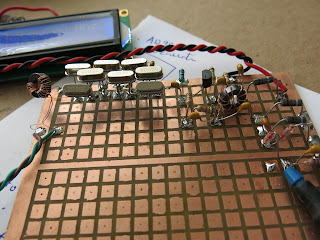
Now I needed a test board to build the filter , the matching input attenuator and a load with an amplifier to monitor the output.
I whipped up a pattern with ExpressPCB
software and ironed onto a pc clad the toner.
Subscribe to:
Posts (Atom)


