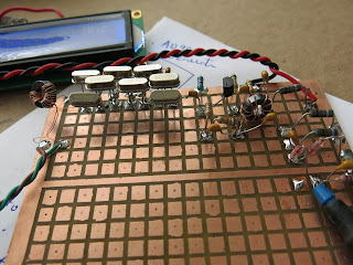
Fired up the RF generator and used my $20 dollar ham fest bought 20Mhz oscilloscope as the detector.
look like the band pass is around this frequency.
the reading was barely there on the scope . the sensitivity of the scope at max 5mV/cm and the 20Mhz range at the edge. Boy, this is going to be unusable data collecting.
I just step through the RF generator range at 100 Hz steps from 19.994 to 19.999 mhz.
the scope blurr shows it blinked very fast indicating the filter is sharp.
I must add an amplifier to this to buffer and amplify the signal.
Took a quick reading on the input side of the filter and the output side readings. te input was 150mV and the output was 60mV.
20 Log 60mV/150mV=-7.96 db loss
time to build an amplifier with 50 Ohm in and 50 Ohm out. remembered VK5TH site has one circuit.
http://vk5tm.com//homebrew/dds/dds.php
click on the schematic to enlarge and click back to the blog
click data t o view
built the amplifier and added the diode detector to get a finer reading. the scope was useless with 5 gradient to a centimeter in reading the changes.
The Arduino RF generator from AD7C's site
http://www.ad7c.com/projects/ad9850-dds-vfo/
here is the result plotted. It has a huge ripple but the sides looks impressive . and the bandwidth is too narrow for SSB use.
so back to more experiments testing loading . Maybe the cause of the ripple from the input and output side and change the capacitor bypass C to adjust the band pass width .
need a amplifier with more gain and high input impedance without loading the filter so that the filter is terminated with a plain resistive load.
mean while had enough today "BASTARD" as in Soldersmoke Blog . Feel like going to was some dishes and relax. I am suppose to be retired.
TO BE CONTINUE..


No comments:
Post a Comment